Welcome to my personal website, "33plymouthcar.com"
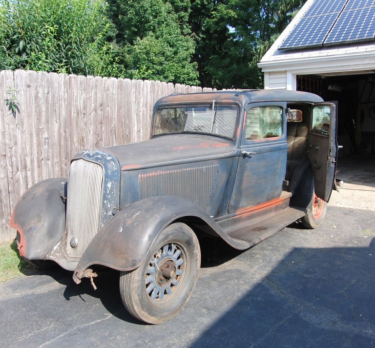

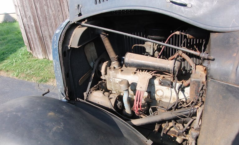

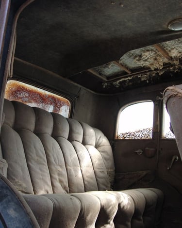

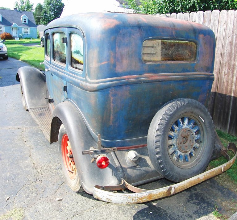

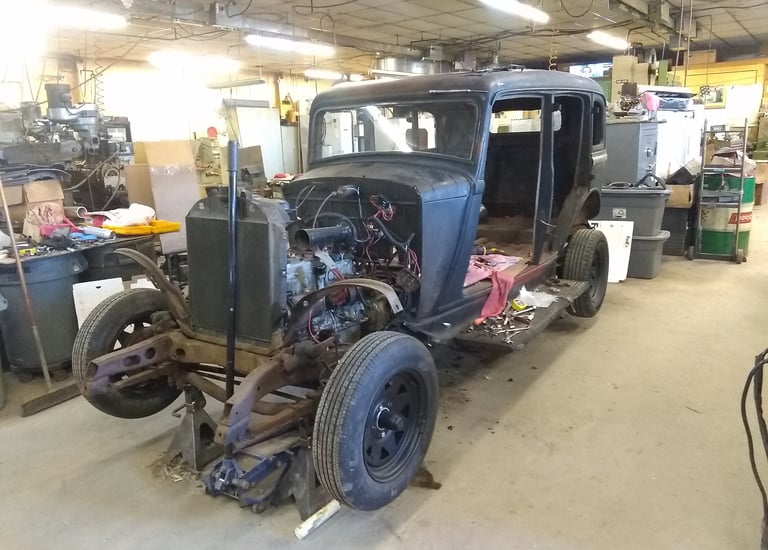

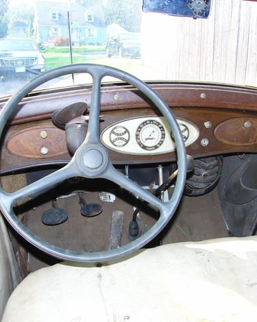

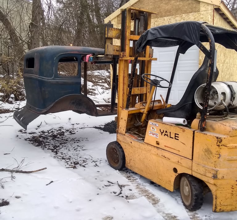

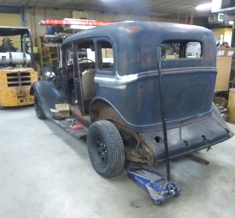

5 Pictures Above: These pictures show how it looked when it was was delivered in August of 2018. The key was still in the ignition, the 30 hour clock mounted in the rear view mirror would later work with a cleaning and new windup string. The rear window shade was still there, I would later discover all the gauges still worked. Note the defroster fan on the steering column. The car was all there, and in good shape for it's age.

In February of 2019 I moved the car to my machine shop to work on it there. Before I started taking it apart I had a friend video my last ride to show you how well it ran. YouTube Link https://youtu.be/NXEVARb7ajc
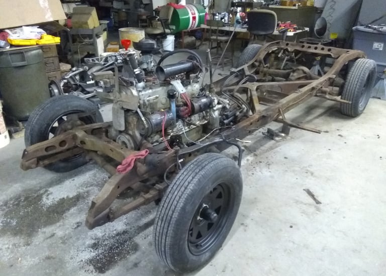

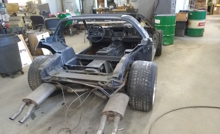
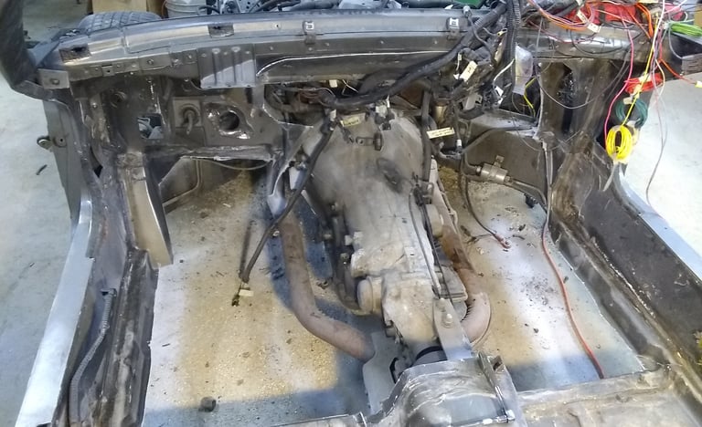
4 Pictures Below: Started taking the car apart.
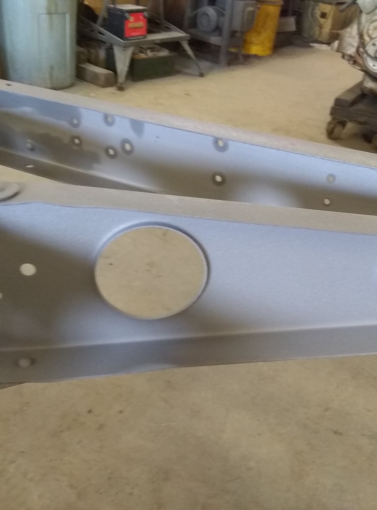





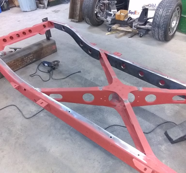



4 Pictures Below: Once everything was taken apart, it was time to clean things up. I sent the frame out for blasting.
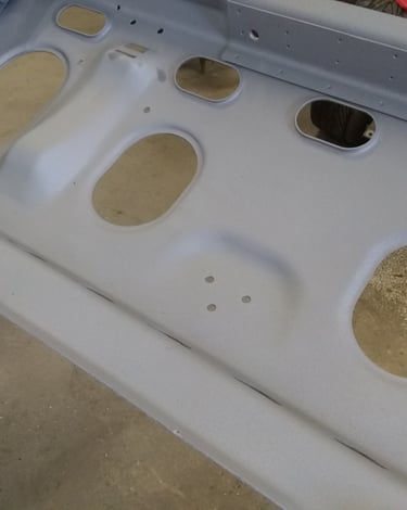
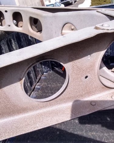
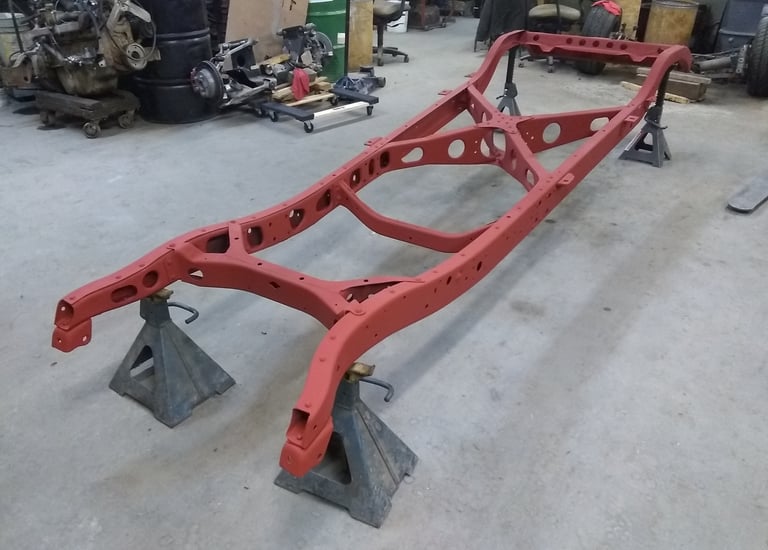
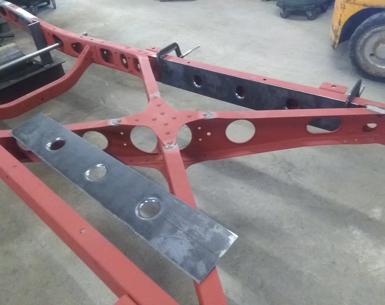
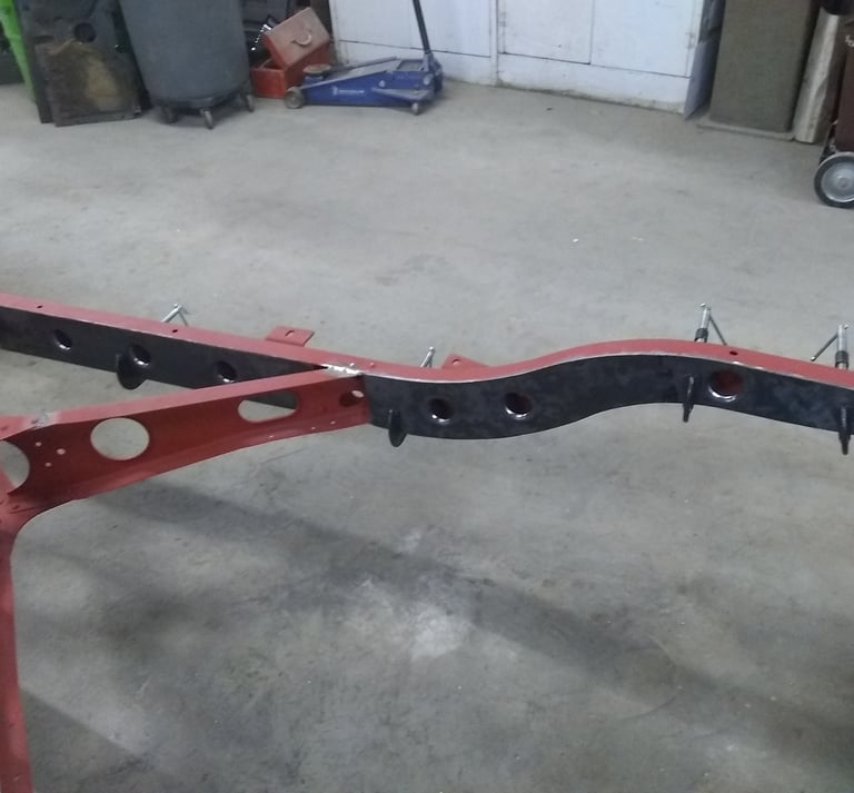
4 Pictures Above: After blasting, I cleaned and sprayed the chassis with an acid etch primer. This primer contains Phosphoric Acid. When applied to iron oxide, (rust), it acts as a rust converter. Phosphoric acid converts the iron oxide that may be left on the surface of the frame, into an inert layer of ferric phosphate. This primer is also a weld through primer. No need to grind the surfaces to be welded.






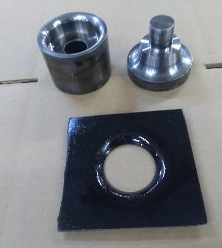
4 Pictures Above; I made a set of dies to form the flanges in the steel panels used to box the frame. This adds strength to the panels. I TIG welded them in place, carefully stitch welding small sections at a time as not to overheat and distort the frame. and dressed all the welds for aesthetics. The frame was checked for squareness and mounted in adjustable fixtures at each end to maintain the frame in a flat and level position during welding, and construction.
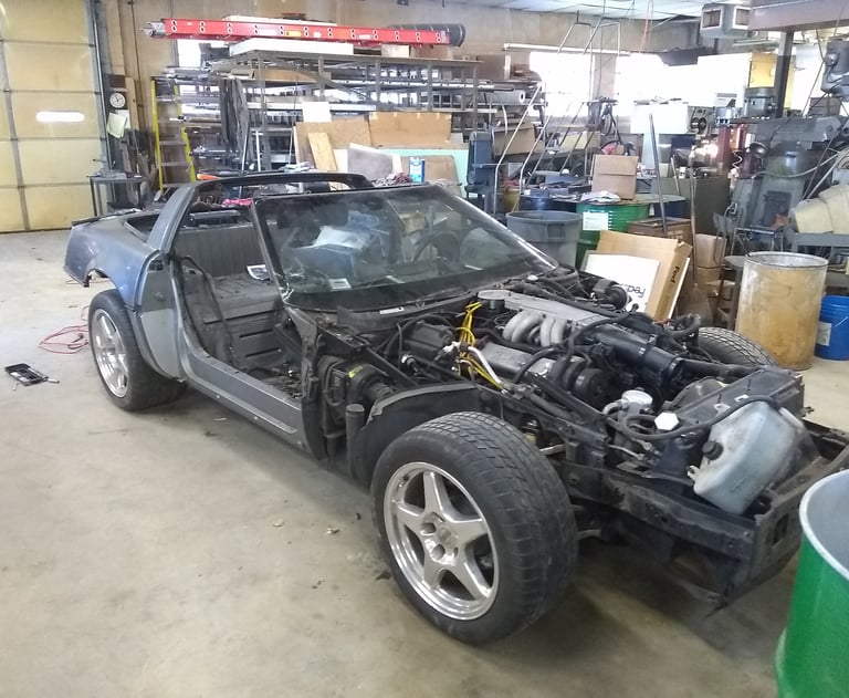
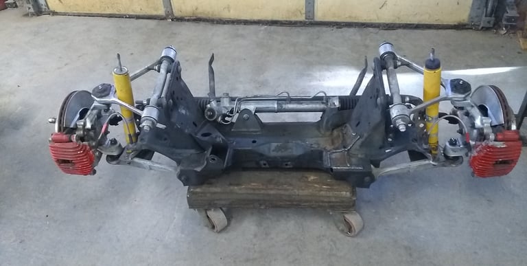
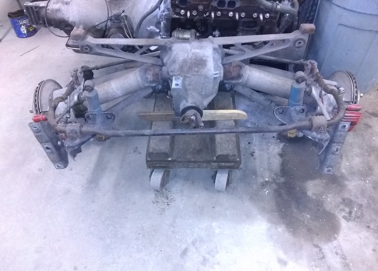
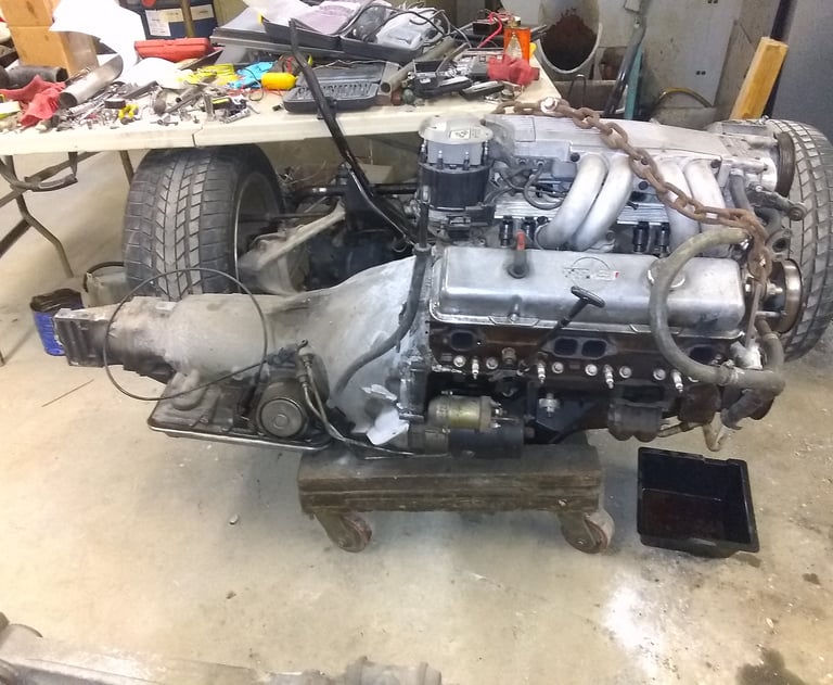
6 Pictures Below: Once I determined I wanted a RestoMod, I had to decide on an engine, drive train, and suspension. After some thought, I bought a complete, and drivable, 1985 C4 Corvette. I took the engine, drive train, independent front, and rear suspension, and figured I would try to put this in the Plymouth.
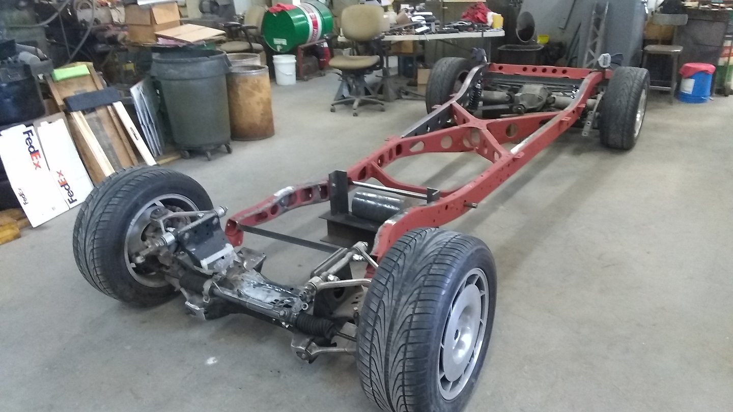
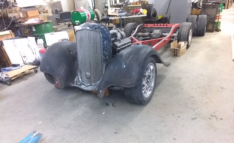
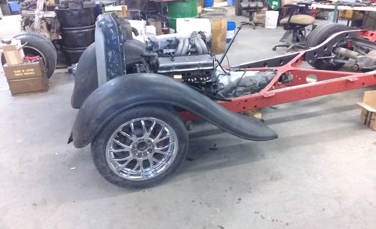
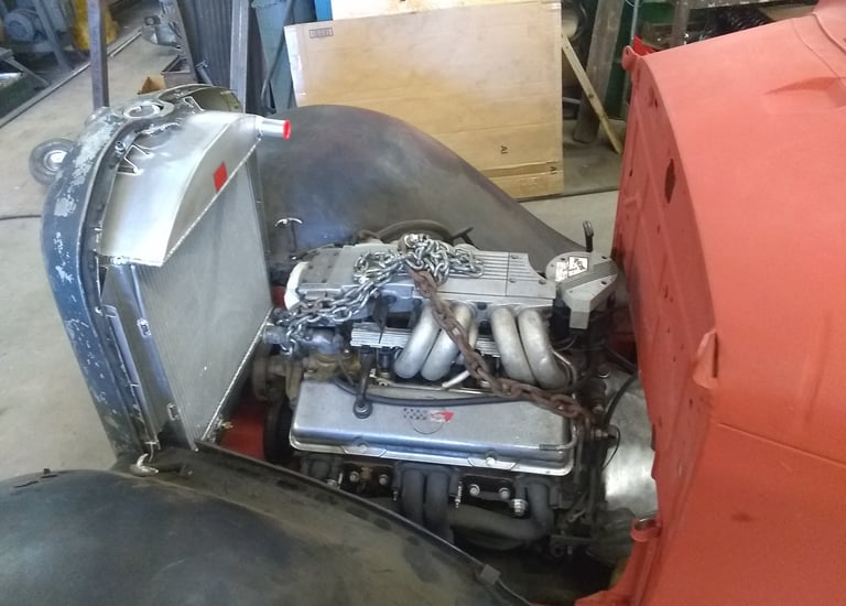
3 Pictures Below: After mocking up the front fenders, front and rear suspension, and engine. I needed to reduce the width of the front and rear wheels by 3 inches, and move the front wheels back 2" for aesthetics.



As I make progress I will be updating the website. I can be reached for comments or questions at, imbolo1957@gmail.com
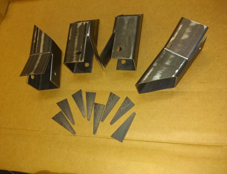
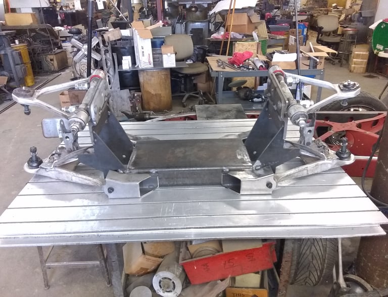
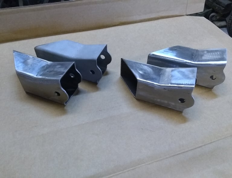
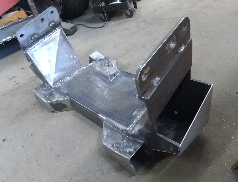
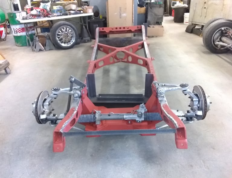
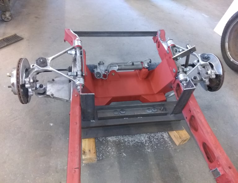
6 Pictures Below: When you narrow a Corvette front end, you can't use the original rack and pinion or the original cross member. I had to cut and weld the rack and pinion, and had to build a new cross member. I didn't want to use the Corvette mono leaf spring because of it's limited adjustment. I wanted to go with coil over shocks to increase adjust-ability. I did cad drawings for the components, and used a Wire EDM to cut them out before welding. The original geometry from the Corvette front end was also documented on cad to later reproduce.




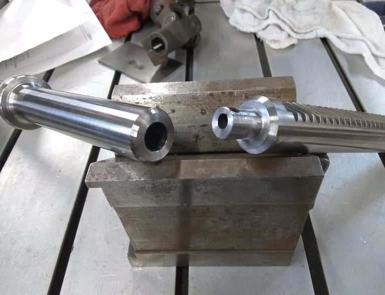

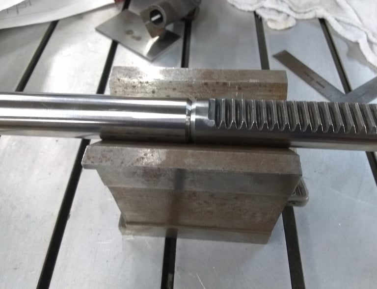



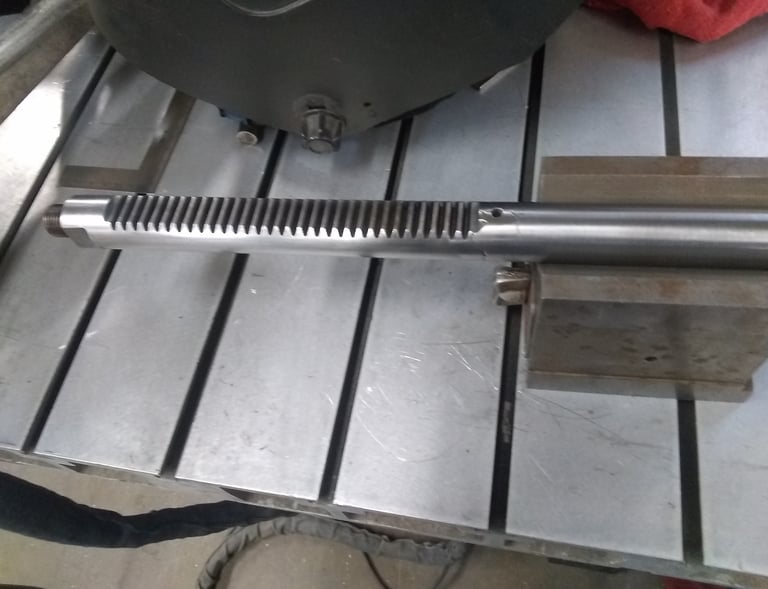

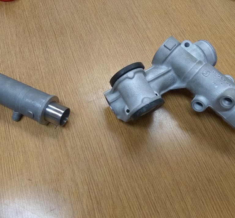
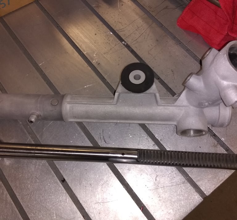
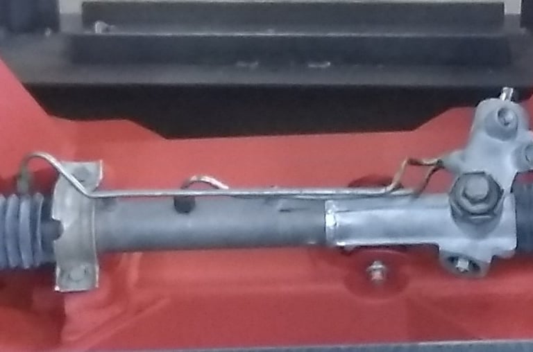
6 Pictures Below: The Rack was cut and machined to make a male/female joint with a snug fit before welding. While welding, the rack was continually checked on v blocks to maintain straightness. After welding the OD was ground and the air transfer cross hole added. The aluminum housing had to be shortened also. It was cut, and a thin wall steel sleeve was pressed in, to maintain alignment, then welded together.



LEFT Picture: The Rear Suspension had to be narrowed by 3". The rear axles had to be shortened 1.5" each. I bought a second set to mock up to make sure I got the length right before I cut the originals. I also would have to make new shortened camber adjustment bars, and adjustable 4 link bars with heim joints.

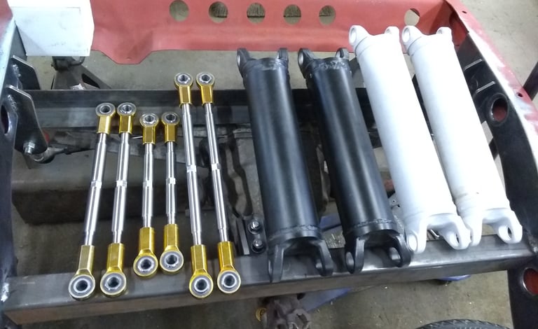



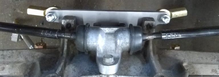




Below Picture: New adjustable Tie Rods and mount had to be made also. The old and new are in the picture. The tie rods have to be shortened to match the length of the axles, to avoid toe-in from changing as it travels through the the stroke of the suspension.
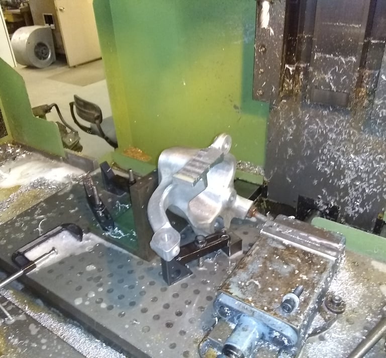
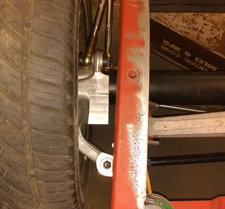
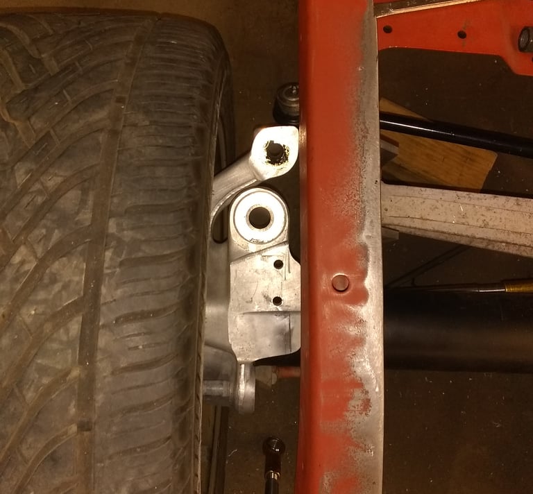
Above Pictures: After narrowing the suspension, the spindle knuckle would hit the frame as it traveled through it's stroke. The knuckle was machined to make clearance. The tie-rods were mounted on top of the knuckle, and would hit the frame when the suspension traveled through it stroke. They had to be inverted and mounted from the bottom. The tapered hole had to be bored, and a stainless steel bushing pressed in to mount the new tie-rods with heim joints.
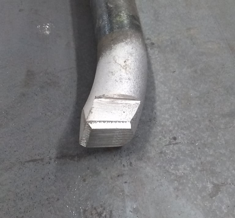
Above and Left Pictures: The original sway-bar had to be shortened to fit. The sway-bar had flats milled on the ends, custom levers were designed, cut on a Wire EDM, and then welded on the ends of the sway-bar. New mounts were made and weld on the frame.

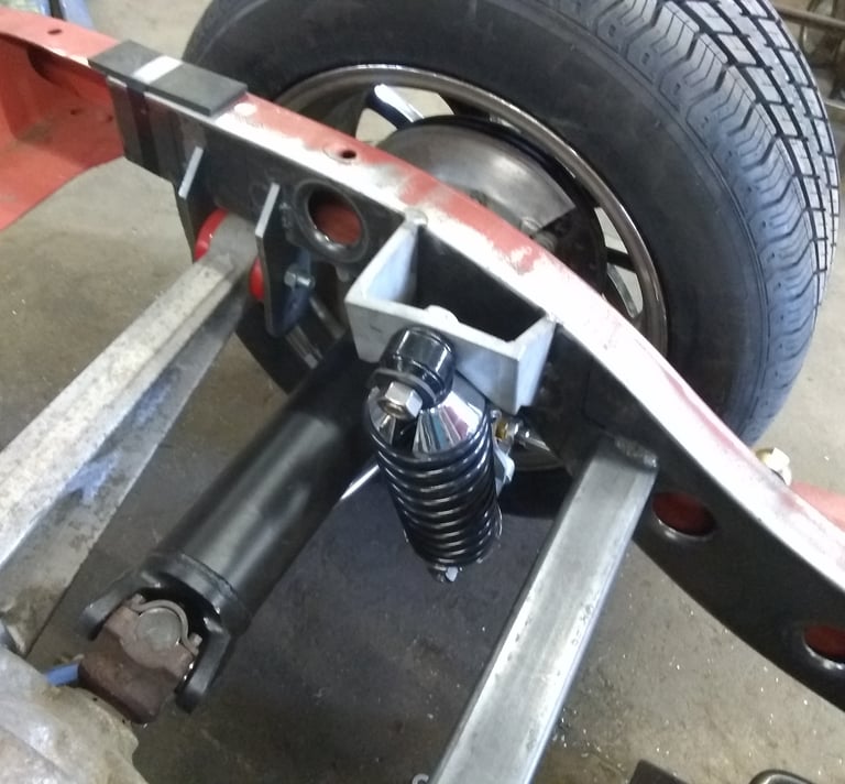
Right Picture: The bat-wing mounts and coil-over mounts were CAD designed and cut on a Wire EDM, and welded to the frame. A 2"x3" cross member was added to the frame also.
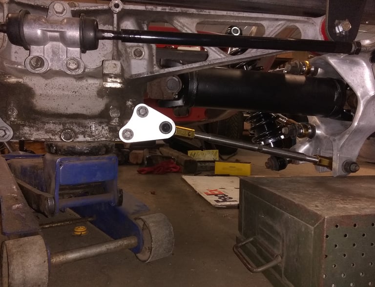

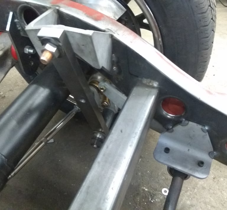
Left Picture; Custom made camber bar mounts had to be designed and cut on the Wire EDM.
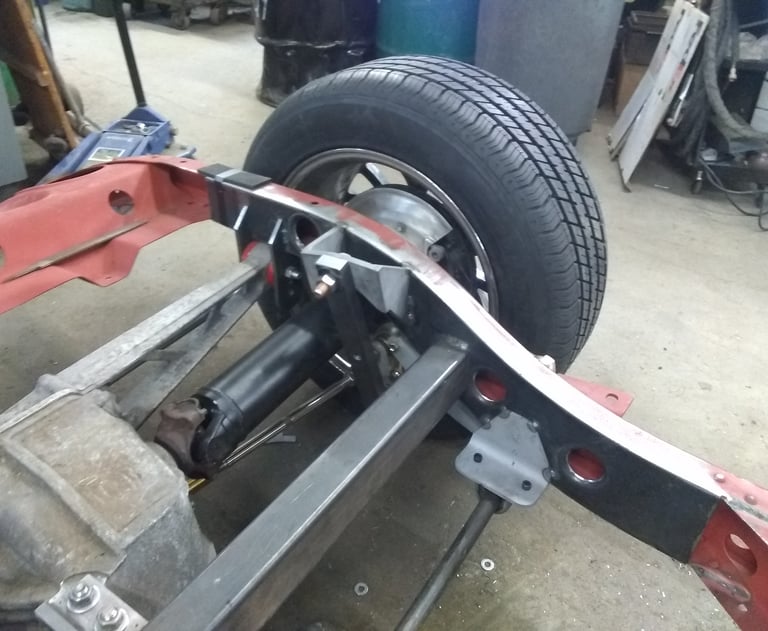

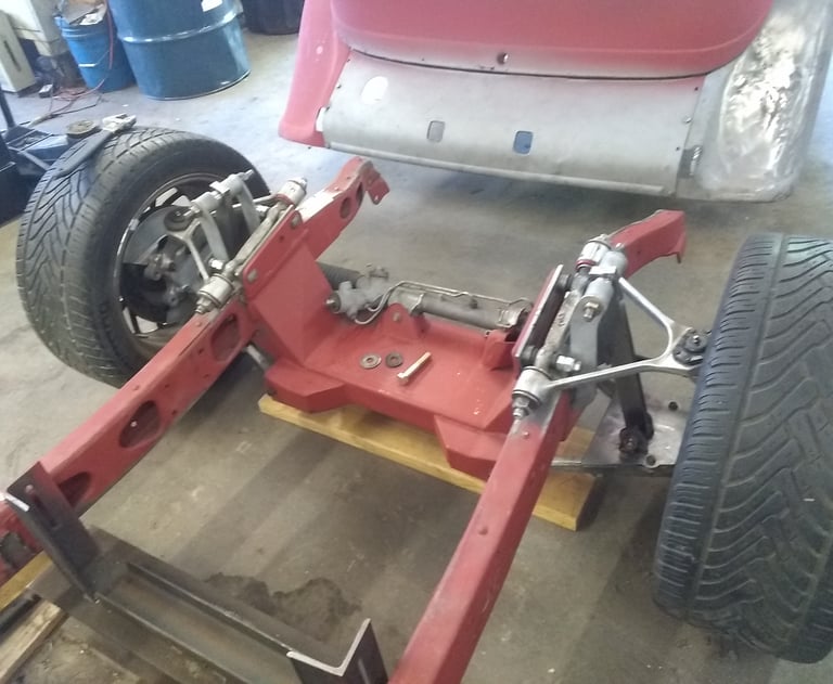

Below Pictures: The coil over shocks have been replaced by steel bars, with hole spacing set at ride height. These will be left in place, and used for mock up. I will send the chassis out for a 4 wheel alignment, prior to mounting the body to make sure I didn't mess up!
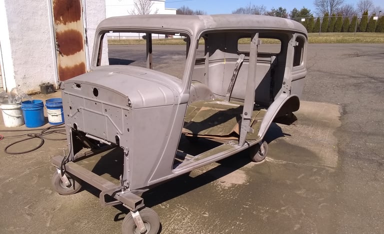

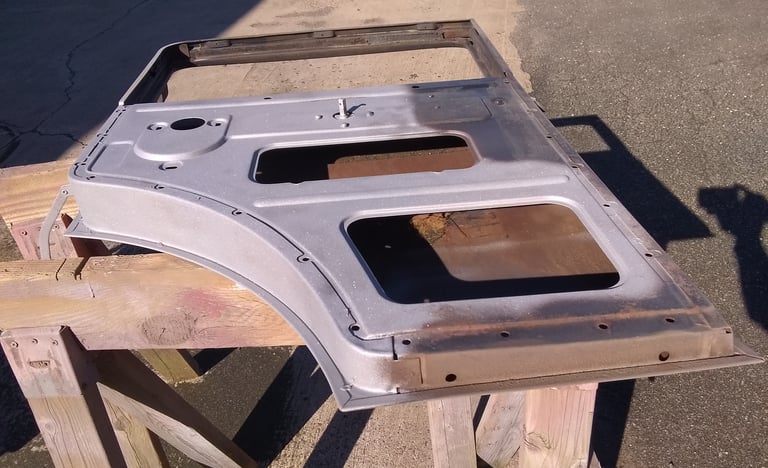

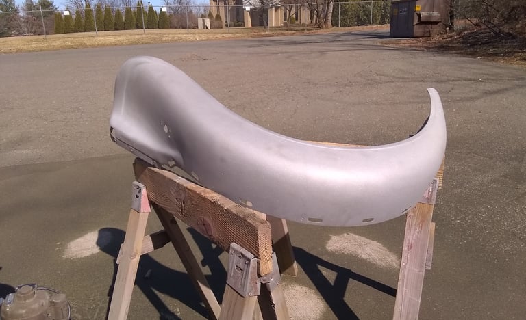

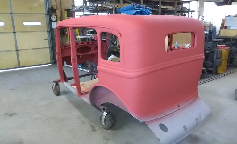

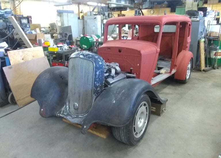


Below 4 Pictures: I decided to blast the body parts myself. They cleaned up nice, and were primed with the acid etch primer.
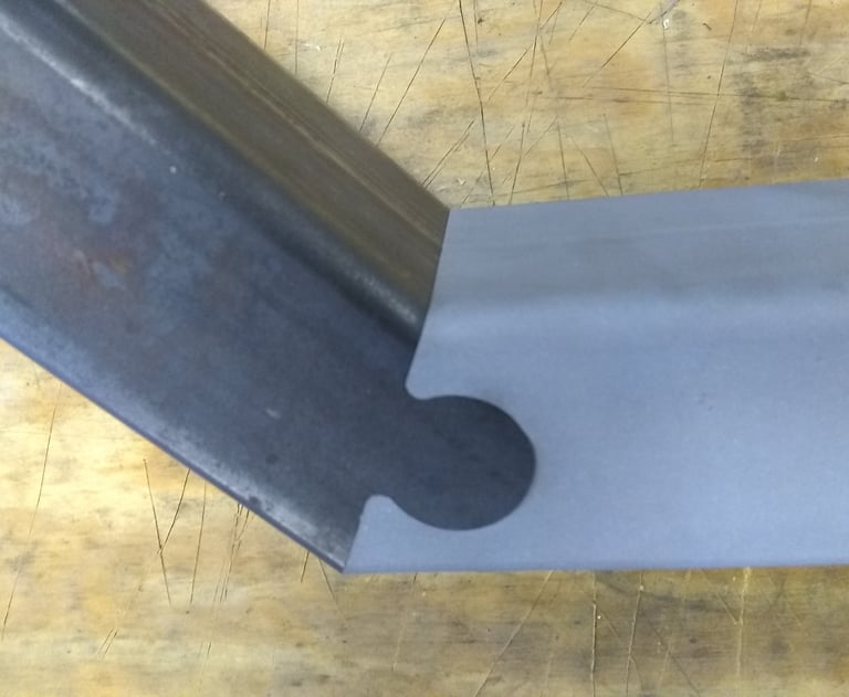
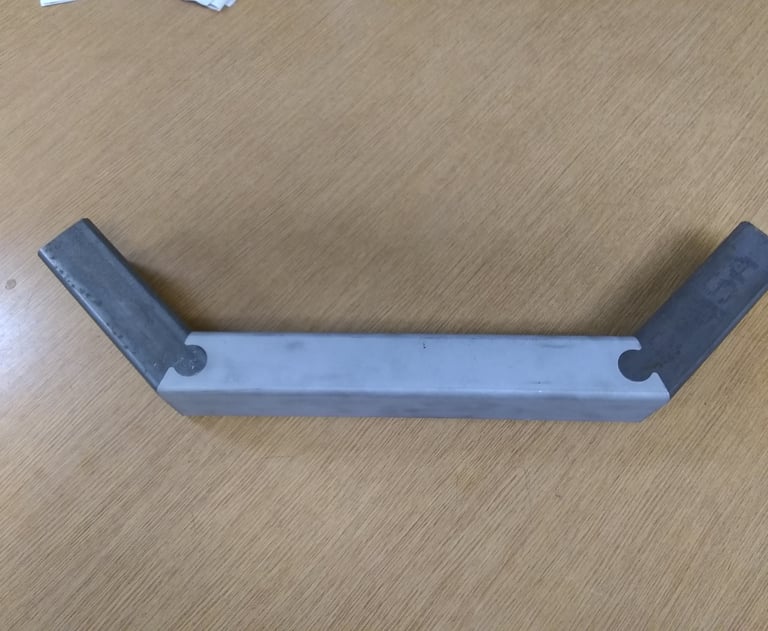
Below 4 Pictures: I mocked up the engine position so i could design the cross member, and motor mounts. To increase the strength of the cross member joint I used the Wire EDM to create an interlocking joint prior to welding. The joint is so precision it has to be tapped together with a mallet.
